
Enclosures: TeenyTinyHouse
- isabellerieken
- Feb 23, 2020
- 4 min read

Updated: Oct 1, 2020
Prompt: Build an enclosure for an electronics project using any tool(s) or technique(s) you like. Make sure that you can get back inside to make repairs, change batteries, modify, etc. The enclosure should have multiple components: buttons, switches, sliders, connectors, display lights, dials, etc.
Concept: I wanted to create a wood enclosure in the shape of a small house with frosted acrylic for the roof so that LED's mounted in the bottom would shine through and the enclosure would act as a little night light.
Materials: 1/4" thick wood, frosted acrylic, perf board, mountable on/off switch, 12V power adapter, LED strips.
Process:
Prototyping (Day 1):
I did a few cardboard cutouts with the laser cutter to figure our my design. After the first one, I realized the enclosure was too large and I wanted to work with smaller pieces. For the third prototype I was just playing around with shape. Also note the backdoor that I originally wanted as an "opening" into my enclosure (more on that later).


Getting the Pieces (Day 2):
Shopping was not an easy task since I had many locations I had to go to: Canal Plastics, Blick, Tinkersphere, and Bruno's Hardware. This day I went to Blick to get the wood (after my amazon order was delayed and I accidentally sent it to California...whoops) and canal plastics so I cut out my basic building blocks. Julia (thank you!) went to tinkersphere and helped by picking up some materials I needed later.
I cut out these pieces first (the switch was just for fitting purposes):

As you can see I still had a door at this point and I had glued some wood blocks on the side pieces of the house. I wanted to do this step first so I could start assembling the house asap. The wood blocks I cut from a scrap piece that was pretty straight as far as I could see, so it also helped with 90 degree angles. I glued the front and the side pieces together, leaving the back open so I could install the electronics later.


So now, the door. I had bought a small hinge thinking it was really straight forward. I soon realized, that it took special techniques to install the hinge if I wanted it to be hidden.
I thought I came up with an ingenious idea when I laser cut a space for the hinge. But the same problem persisted... the wood's thickness prevents it from turning very far. When they professionally install them, they somehow leave a gap between the door and the wall. I watched a few videos, but was still perplexed and decided the door was a waste of my time and pretty useless.
There was also another problem... the screws that held in the hinge had depth and that meant I couldn't glue this back piece onto the rest of the house. So really, I didn't give this door enough thought and it is a challenge I may want to take on in the future, but not in this project.
I ended up cutting another piece, without the door and moved on to the electronics.
Electronics and Assembly (Day 3):
The most frustrating day of all.... Thank you so much DAVID!!!
I needed a simple circuit: power, switch, and LED strips. But, I didn't have power. Because the LED strips required 12V, the shop staff recommended that I get a 12V power adapter and DC jack. But, it was late at night so I couldn't buy one and I had no idea how to use one. Luckily the junk shelf game to rescue and I found exactly what I needed! No better feeling. To make sure the pieces work I just tested them with the multimeter.
First, I practiced lighting 1 LED strip, which worked. Next I had to attach all the LED strips in a series circuit and tried those with power and they also worked! The next step was inserting the switch into the circuit.
I was using a perf board for the first time which was a whole different challenge. So when I had the switch put into the circuit, the lights never turned on. I had tested the switch previously, but at this point, electricity wasn't flowing through it, so I switch it out with a switch from the shop and it finally worked! I drilled a hole on the side for the power jack to stick out of and mounted the perf board on some foam board so that it could be take in/out. I also screwed in the switch and glued down all the LED's before attaching the back piece.


Next, I cut out my acrylic pieces that would fit into the windows, door, and roof areas.

For the windows and door I smeared a very small amount of hot glue one inside edge and then push the pieces in from the front. They didn't need a lot of support because they were fairly snug in their cutout slots.
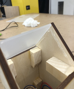
At this point, I realized a good access point could be the roof pieces, which easily come out. I had trouble finding a really "nice" way to keep the roof pieces in place. I ended hot gluing these supports that were also a little take and gripped onto the pieces well. Also, the original pieces I had cut were a little long (and my box was a little crooked) so I had to shape one a little with the sander and then recut the other piece so they could nestle in together. The supports temporarily work well if the lamp is just stationary.


My Final Product:
I'm pretty happy with how it turned out. It's not super straight and even on all sides, but I still love and it and learned A LOT from this project.


Comments